Green Circuits’ process for designing and fabricating high-level printed circuit boards avoids common PCB failure modes that often occur in the electronics industry.
Shortcomings during the initial manufacturing process lead to many printed circuit board failures. The electronic product may also fail in later stages of development.
The Green Circuits team believes good design minimizes the chances of common PCB failure modes occurring either before or after the printed circuit board leaves our facility. Our trained engineers identify potential design problems and correct them before production.
Quality materials make a significant difference in PCB performance. Poorly made components, for example, may ooze corrosive fluids and cause short circuits. We produce a comprehensive bill of materials to assure our partners that we use only high-grade, readily identifiable materials when fabricating their printed circuit board prototype.
Finally, stringent testing eliminates any PCB failure modes that surface once production begins. Green Circuits’ loyal clients know that every printed circuit board leaving our facility will perform reliably and according to specifications.
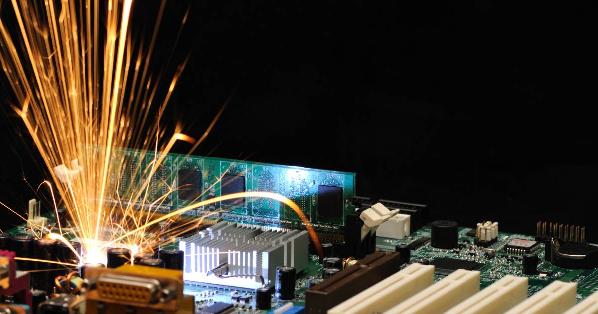
Even a well-designed PCB can have problems. Here are some reasons fail modes happen:
Every PCB manufacturer encounters challenges. Green Circuits technicians are trained to identify issues before they become a problem.
If your business seeks to avoid common PCB failure modes, contact Green Circuits. We’re Silicon Valley-based designers, assemblers, and manufacturers of printed circuit board prototypes. Call 408-526-1700 today to speak to one of our engineers. You may request a quote online, too.